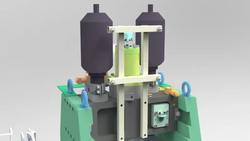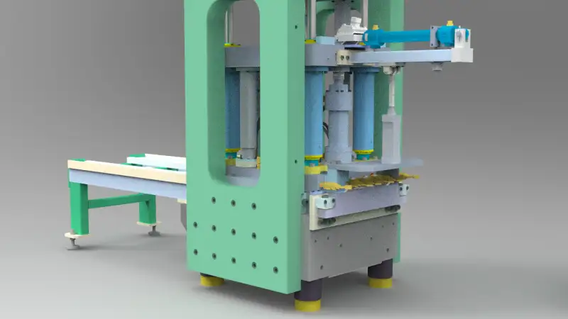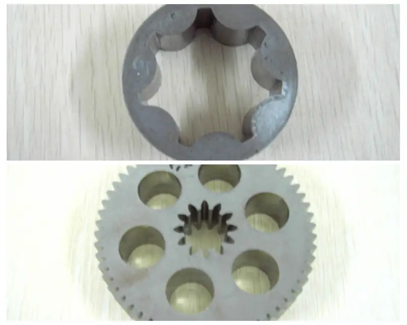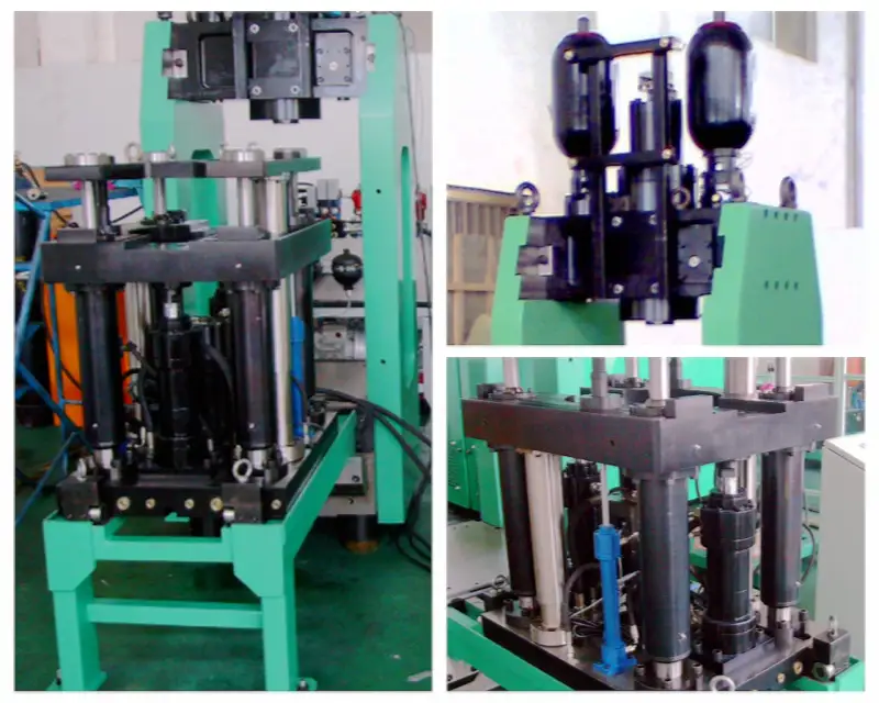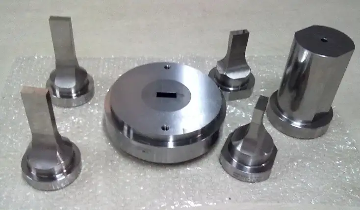
High density powder metallurgy products are produced by high speed impact compaction technology, which is also suitable for finishing or re pressing of powder metallurgy products. The structure includes an upper template, a concave template, a guide pillar, a guide sleeve, an upper die punch, an impact block, an upper die guide device, a concave die and a lower die punch; a guide pillar and a guide sleeve are installed between the upper template and the concave template, the upper die guide device is installed on the upper template, the concave die is installed on the concave template, and the lower die punch is matched with the concave die; the upper die guide device includes a guide sleeve, a block and a gland, and the guide sleeve is installed on the upper template In the middle guide sleeve installation hole, the block is installed in the middle and upper position of the guide sleeve, the upper part of the block is equipped with a gland, and the gland is fixed at the upper end of the guide sleeve; the impact block and upper die punch are installed in the guide sleeve of the upper die guide device, and the impact block is installed on the upper part of the upper die punch.
Working Flow
- The hydraulic cylinder pushes the shoe and powder to the loading position
- The die rises and the powder is filled in the process
- The boot is pulled back to its starting position and re powdered
- The die rises a certain distance to prepare the upper die for filling into the die in the next step
- The upper die base descends and the upper die slides into the die
- The hammer head descends a certain distance and preloads, then returns to the hammering position and waits for hammering
- The hammer punches the upper die, and the powder is formed
- After punching, the hammer still exerts pressure on the upper die, the die drops to its starting position, and the pressure is withdrawn
- Both return to the die base and start to run with the punch
- The cylinder pushes the manipulator to the manipulator to reach the part
- The manipulator grabs the shape, and then the manipulator returns to the starting position
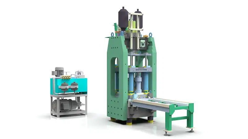
The design based on CREO4.0, and the original files are from CREO4.0, but we converted it to Solidworks 2017 and Inventor 2019 files for you, besides, stp format file we provided also.
The total size of the zip file is 200 MB, we hope the design project can bring you inspiration and save your design time.
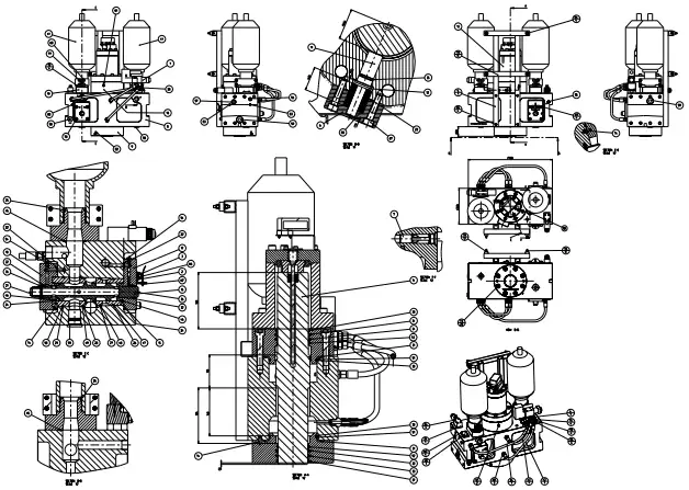
Download the 2D drawing of Punch assembly