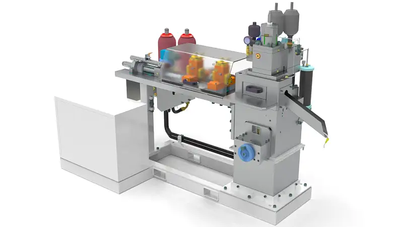
Design of Hydraulic High Velocity Cutting Machine
Cutting machines are mainly used in the metal and non-metal industries. Generally speaking, the classification of non-metallic industries is more detailed, such as water cutting machines and saw tooth cutting machines for cutting stones; laser cutting machines and blade cutting machines for cutting fabrics or plastics, and chemical fiber products; and plasma cutting for metal materials Cutting machine, zigzag cutting machine, flame cutting machine and so on.
At present, in the field of bar material cutting, mainly saw tooth type cutting machines are used. This type of cutting machine has advantages when cutting bar material with a diameter greater than 40 mm; in the field of bar material cutting with a diameter of less than 40 mm, the cutting method is not only sawing, There is also mechanical or hydraulic impact shearing.
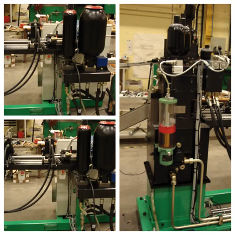
In order to meet the requirements for rapid and precise cutting of slender bars, metal wires and profiles in production, a hydraulic impact bar rapid cutting machine is designed. This design specifically describes the design principles and corresponding hydraulic control principles of the three parts of the cutting machine’s hammer head, buffer and feeding system.
1. Design principle of cutting machine
A large amount of plastic work produced by a material under large deformation leads to a local temperature rise of the material. The local temperature rise further leads to the thermal softening of the material, resulting in greater deformation, which eventually leads to the destruction of the material. It is an important failure mode that often occurs in metal materials. The cutting machine is designed according to this basic principle, and its working process is as follows:

Step 1: The feeding system feeds the bar stock.
Step 2: the hammer head impacts the mold, the bar material is thermally softened and cut, and the bottom buffer mechanism absorbs the kinetic energy of the mold to stop it smoothly.
Step 3: The buffer mechanism ejects the mold and restores it to the initial position. The feeding system feeds again and continues to repeat the above steps.
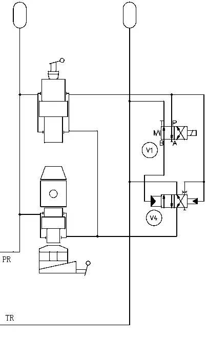
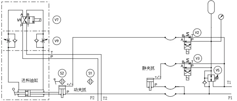
A new design method of hydraulic impact bar cutting machine is proposed. The design mainly includes three parts: hammer head, buffer and feeding system. Through the actual cutting test, the number of bars with a length of 25 mm per minute is 150, and the length error is less than 0.05 mm. The design of impact cutter has enlightenment and reference significance to the field of cutting machine design.
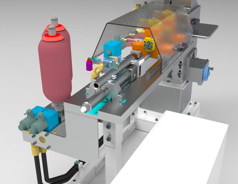
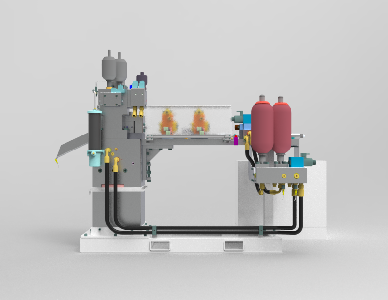
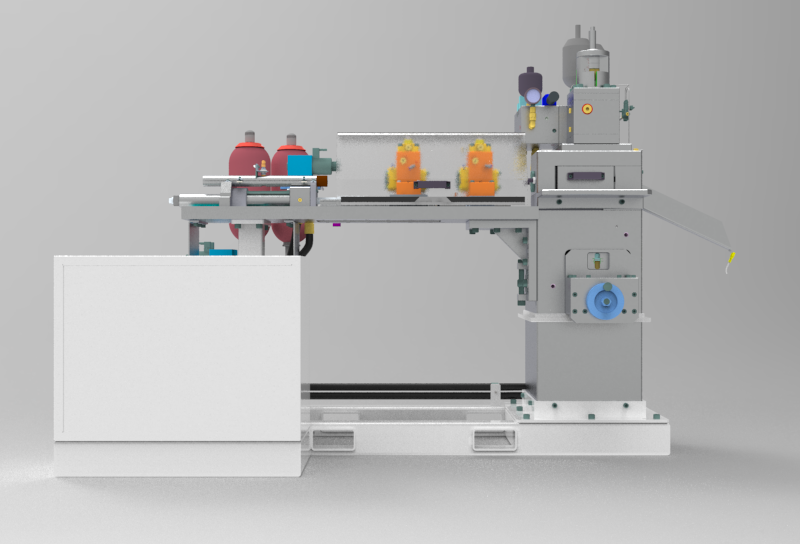
2. 3D digital model
The design based on CREO 4.0, features can be edited for your improvement. Including step format file. File total 55 MB.
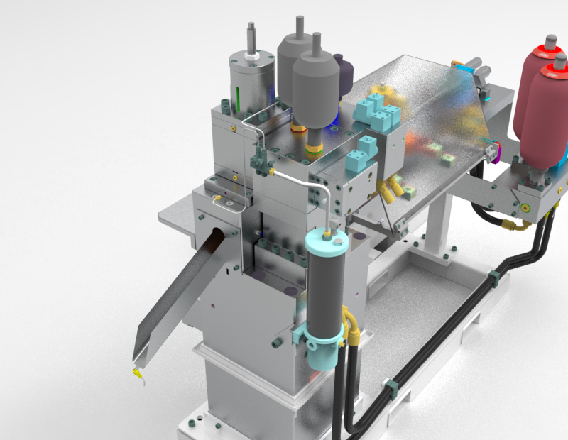
3. Reliability analysis of cutting machine system
In terms of improving the reliability of the control system, there are mainly two types of technologies: one is to prevent and reduce the occurrence of faults, called error avoidance technology; the other is to keep the system normal when a certain part of the system fails Working technology is called fault tolerance technology. Error avoidance technology is the technical foundation of system reliability, and fault tolerance technology is the remedy and guarantee measure of reliability. The designed cutting machine control system adopts the following aspects to improve the reliability of the system:
1. Simplification of the system structure. The simpler the system structure and the fewer components, the higher the reliability of the system.
2. Improve the anti-interference ability and environmental adaptability of the control system.
