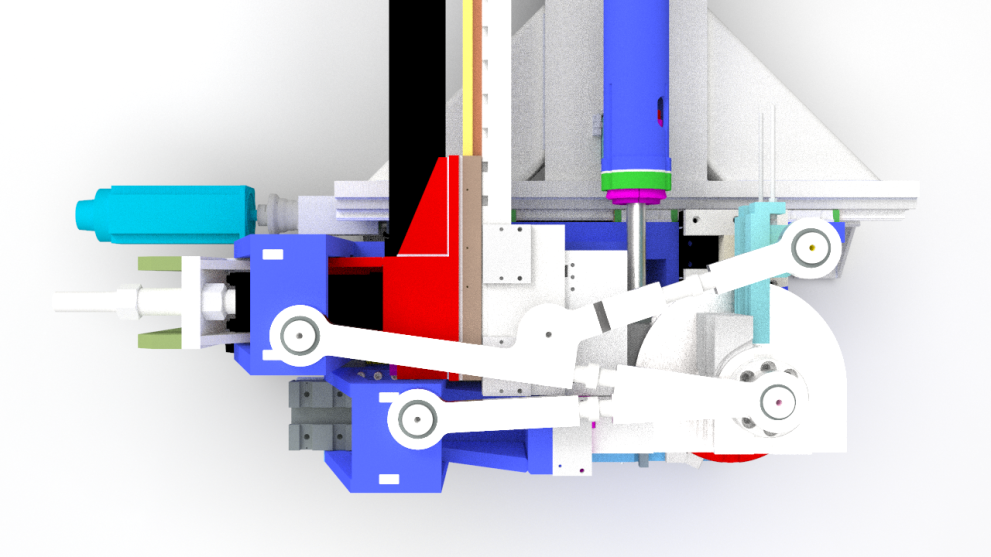
3D Design Model of CNC Automatic Pipe Bending Machine
The basic working principle of the pipe bender is to apply bending moment through reasonable fulcrum and stress point to make the steel pipe plastic deformation, so as to realize the purpose of cold bending of steel pipe. The lower die is located in the front of the pipe bender. It is suspended on the frame by hydraulic cylinder in floating state. The inner tube is put into the steel tube and placed in the center of the upper die. The inner tube expansion block is supported against the inner wall of the steel tube, so as to avoid abnormal deformation of the steel tube in the bending process.
When bending, the horizontal hydraulic cylinder is operated to drive the inclined block to make the outer wall of the steel pipe contact the upper die, which is fixed in the middle of the frame. Play a fulcrum role. The clamp is located at the tail of the pipe bender, which can clamp one end of the steel pipe when bending, so that the steel pipe will not move in the bending process. At the same time, it can adapt to the angle change of the steel pipe due to the axis deflection. Under the action of the main oil cylinder, the steel pipe is subjected to transverse force when the lower die rises. The center of the upper die and the clamp are the reaction force of the support. When the tensile stress of the lower wall of the steel pipe reaches the yield limit of the steel, the steel pipe will produce plastic deformation. It will be bent in turn along the curve of the upper die.
This 3D design model based on SolidWorks 2017, and STEP file also provided for you to open it by other 3D software programs. The file size is totally 97 MB.


