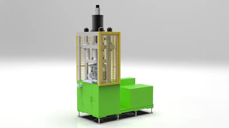
3D design model of punch boss hydraulic press parallel bar horizontal side processing machine
Technical requirements of double cylinder horizontal side processing machine
The equipment is mainly composed of mechanical system (boss forming and punching device, positioning device, box and hydraulic station, etc.) and electric control system and pneumatic part.
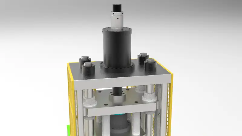
Boss forming and punching device
- It is composed of boss forming and punching die, boss forming and punching cylinder, feeding mechanism and positioning device, die support component, etc.
- Boss forming and punching die: when the main shell is placed on the equipment, the process hole is used for positioning, and the required boss is formed on the boss forming punch after pressurization, and the punching is completed on the boss at the same time.There is a mechanical limit for the cylinder of boss forming die to advance to the position, and the proximity switch is used for sensing and retreating to the position
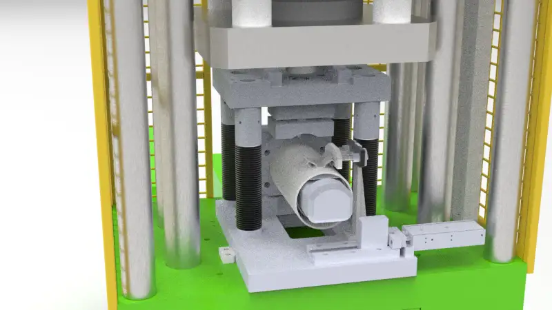
- Forming positioning device: in the process of boss forming and punching, forming positioning device can be used for accurate positioning to ensure the stability of boss forming and punching
- Supporting mechanism: the main shell is placed on the supporting mechanism
- Mold support assembly: after the work body is placed on the supporting mechanism, after starting and pressing, the mold support assembly will automatically advance to support the punching mold, and will automatically return after processing.
Purchase details of mechanical and electrical standard parts
1 PLC Mitsubishi Q series
2 touch screen Mitsubishi
3 Low voltage components Fuji / Chint
4 Pneumatic parts SMC
5 Screw rod HIWIN
6 Track HIWIN
7 a sensor Keenes / OMRON
Electrical control system
All control circuits of the equipment are DC, 24 V (including pneumatic and hydraulic solenoid valves)
The equipment status indicator is used to show the operation status of the equipment.
Green light: normal operation
Yellow light: equipment rest or other
Red light: abnormal or faulty equipment
Electrical cabinet and circuit
Electrical control components are all concentrated in the electrical cabinet and arranged in order. The control components, execution components and detection components are marked accurately and clearly to facilitate future maintenance. The electrical cabinet is sealed reliably, with obvious boundary between high and low voltage.Different potentials.Different colors are used, and the terminal is covered with wiring code.With 220 V terminal block.
There are 10% wiring terminals reserved in PLC, and the solenoid valve is connected with PLC through relay.
All pneumatic parts adopt international brand SMC to ensure the quality and service life and minimize the failure.
Safety
Electrical performance: Grade E, with good grounding.
There are emergency buttons at each operation place, which are obvious and easy to use.
Low pressure working value alarm.
Other safety issues related to the equipment configuration shall be realized by the demander through the management system of the company.
Other requirements
The famous brand of side processing machine includes: equipment name, model, manufacturer, serial number, date of delivery, brief electrical parameters, and the famous brand parameters meet the national 3C standard.
Water and gas path, flow direction, component name, etc.
Labeling
There are clear marks near the installation of famous brand control components, executive components and inspection components.
All famous brands are made of mirror stainless steel or mailing glass, and the font is not faded.
The left and right control valves are clearly marked. (for the convenience of subsequent maintenance, all sensors and external components should be clearly marked, and the corresponding points of PLC should be marked with Chinese characters, and the font should not fade.)
Surface coating
The equipment cover and rack shall be painted, and the color shall be determined by the demander (apple green, apple green, gsb05-1426-2001,28 G01 (national standard color)).
This 3D design model based on SolidWorks 2017, and STEP file also provided for you to open it by other 3D software programs. The file size is totally 73 MB.
Download the Technical requirements here
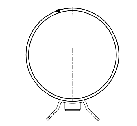
Produced Sample Drawing
Top view of the machine
Front view of the machine
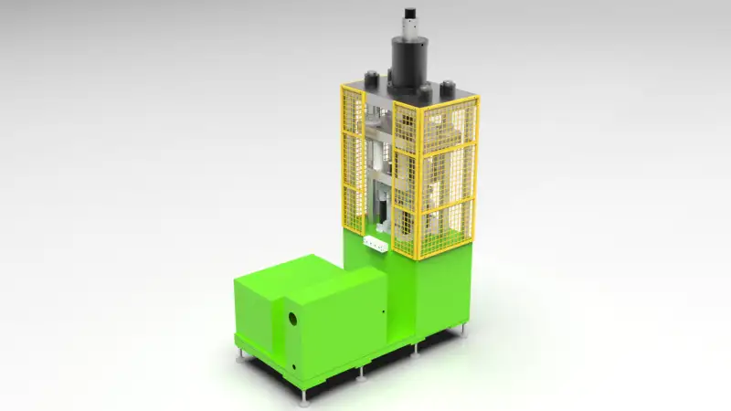
ISO view
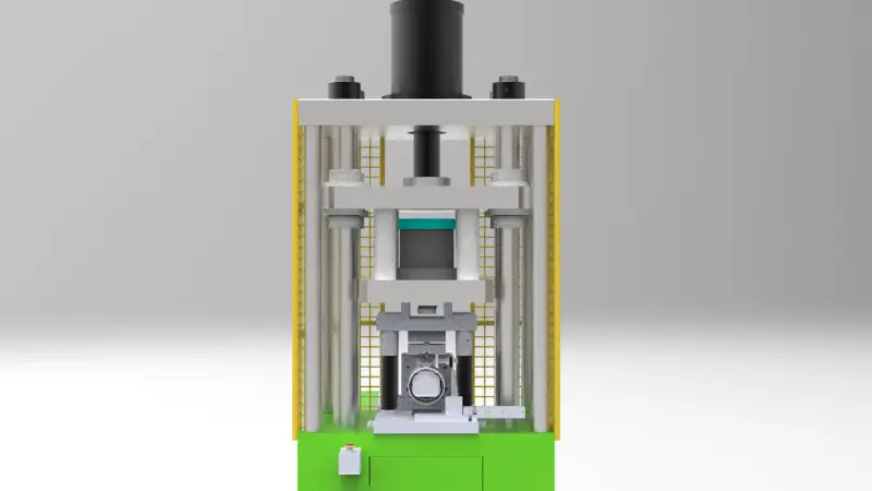
Front view
Related Article:
Hydraulic Lifts
Here is everything you want to know about hydraulic lifts.
You will learn:
What is a Hydraulic Lift?
How do Hydraulic Lifts Work?
Types of Hydraulic Lifts
Hydraulic Lift Tables
And much more…
