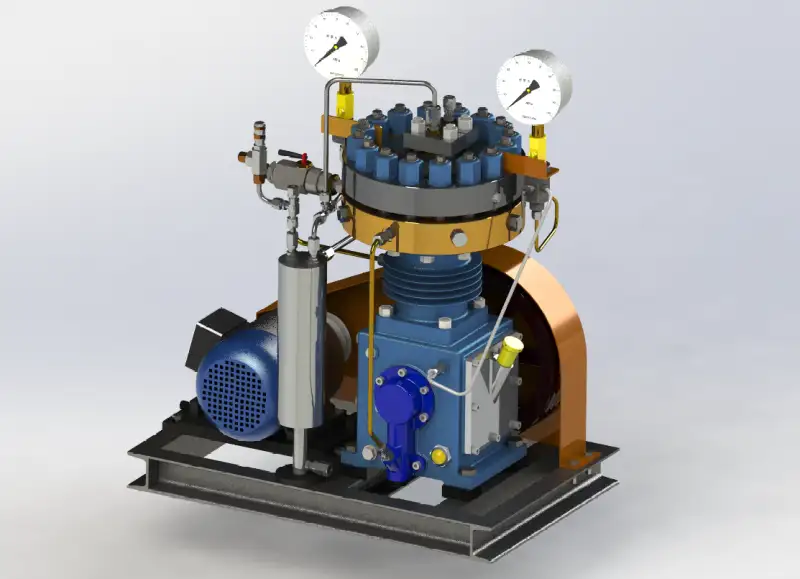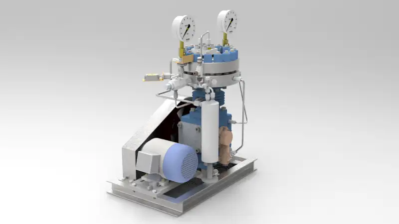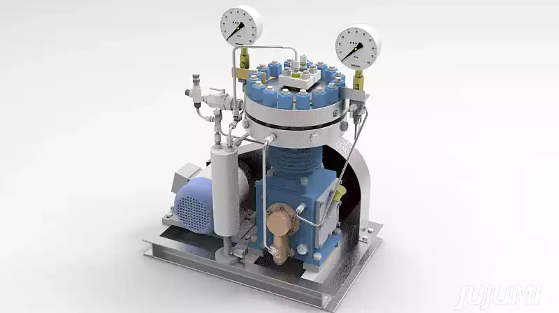
Diaphragm compressor is composed of cylinder block, cylinder head, crankshaft connecting rod, diaphragm, oil circuit, gas circuit, water cooling system and motor drive. It can provide various cooling methods for all diaphragm compressor series products: air cooling, water cooling and forced cooling.
Working principle:
Diaphragm machine belongs to the displacement compressor, which can compress the gas by changing the volume of the air cavity by the deformation of the diaphragm.
A curved surface is machined on the cylinder head and oil distribution plate of the diaphragm head, and the diaphragm sandwiched between the two forms an air cavity and an oil chamber respectively. The air cavity is connected with the suction and exhaust valves installed in the valve hole of the cylinder head, while the oil chamber is connected with the oil chamber in the cylinder block through numerous guide holes on the oil distribution plate. The bolts around the film head fasten the cylinder head, diaphragm, oil distribution plate and cylinder block together, so that The gas and oil cavities in the diaphragm head are sealed without leakage.
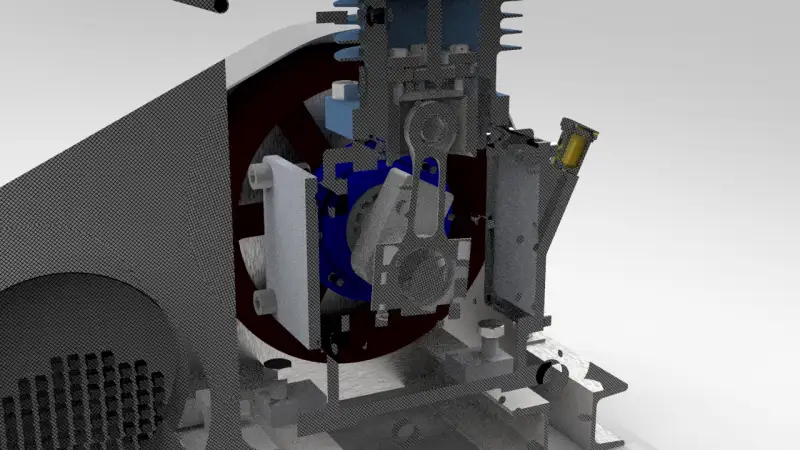
The volume change of the membrane cavity is obtained by the deflection deformation of the diaphragm in the membrane cavity, and the deformation of the diaphragm in the compression process is driven by the oil in the oil chamber. The pressure oil is pushed by the oil pressure piston in the oil cylinder and enters into the oil chamber through the guide hole of the oil distribution plate and acts on the diaphragm, causing the diaphragm to deform in the membrane cavity and change the volume of the air chamber and oil chamber periodically, The reciprocating motion of the cylinder piston is driven by the crank connecting rod mechanism.
The working cycle process of the compressor is: when the compressor is running, when the piston is at the outer dead center, the diaphragm will deform under the action of pressure oil, and then cling to the cylinder head surface, and the gas in the air chamber has been discharged, but there is still high-pressure residual gas due to the clearance volume. When the oil cylinder piston moves towards the internal dead center, the oil pressure in the oil chamber gradually decreases until it disappears, and there is a pressure difference on both sides of the diaphragm. The diaphragm begins to retract and deform under the action of gas residual pressure and its own deformation force. The volume of the air chamber increases gradually, and the high-pressure gas in the clearance of the air chamber expands.
When the air cavity increases to a certain extent, the expansion process ends and the air pressure in the cavity is less than the pressure of the gas to be absorbed The suction valve opens automatically and the suction process begins. When the oil cylinder piston continues to move towards the internal dead center, the diaphragm will continue to deform to the oil chamber side under the action of pressure difference. When the oil cylinder piston moves to the internal dead center position, the diaphragm will deform to the lower limit position. When the piston in the oil chamber starts to move outward again, the suction valve closes, the suction process ends, the oil pressure begins to rise, the diaphragm deforms towards the TDC, the volume of the air chamber gradually decreases, and the gas in the air chamber begins to be compressed. When the compressed gas pressure in the air chamber is far greater than the gas pressure in the exhaust pipe, the exhaust valve automatically opens, and the compression process is completed and the gas is discharged until the oil The cylinder piston moves to the outer dead center, the diaphragm clings to the surface of the cylinder head, and the exhaust valve is closed to complete the exhaust process, thus completing a working cycle.
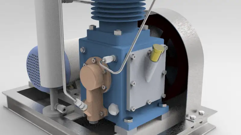
In each working cycle of the compressor, the oil volume in the oil chamber or oil cylinder will be lost due to the leakage of the oil cylinder piston or a little more oil discharged from the pressure regulating valve when the pressure is released. Therefore, it is necessary to supplement the oil into the oil chamber or oil cylinder in each working cycle. The plunger or make-up oil pump installed on the front of the fuselage and driven by the eccentric sleeve at the front end of the crankshaft replenishes oil to the oil chamber at a fixed time (generally at the beginning of the cylinder piston’s inward dead center stroke) in each working cycle.
In the process of each cycle, the amount of oil replenished is usually the amount of oil that will be lost. Therefore, the surplus part must be discharged in time. At the same time, during the compression process, the oil pressure and air pressure should maintain a reasonable pressure difference (generally, the oil pressure is 10-15% higher than the air pressure). Therefore, it is necessary to adjust and control the oil pressure stably.
These spring type pressure regulators are installed on the diaphragm head cylinder block (or oil distribution plate) The valve is used to control the opening and closing of the valve by the spring force in the pressure regulating valve. When the oil pressure in the oil chamber increases and exceeds the specified value due to too much oil, the oil pressure in the chamber will open the pressure regulating valve, drain the excess oil and keep the oil pressure at a certain value, then close the valve under the action of the spring force to keep the operation stable.
- Compressed medium: gas
- Lubrication mode: oil free
- Air displacement: 20 Nm^3/h
- Intake pressure: 1.2-8Mpa
- Exhaust pressure: 15.7Mpa
- Overall dimensions: 640*450*800
- Application: civil, military, industrial, aviation
- Power: 2.2 kw
- Cooling mode: water cooling
- Transmission mode: belt drive
This design model drawn by SolidWorks 2018, the model is detailed design. The original 3D file allows you to quickly modify the design. The step format file is provided for opened by other 3D software. The package size is approximately 78 MB.